Camera Calibration and Lidar Projection
In this tutorial, you will calibrate the onboard camera, undistort captured imagery, and overlay lidar points onto the rectified view. The calibration lets you fuse vision and range data for perception tasks like obstacle detection.
Background
Camera calibration has two parts, intrinsic calibration and extrinsic calibration. Intrinsic calibration is the process of estimating the parameters of the camera matrix. The camera matrix includes focal length, optical center, and distortion coefficients. This information is essential for correcting image distortion. The second part, extrinsic calibration is the process of identifying the relative positions of sensors in order to accurately fuse information from those sensors. In this tutorial, we will map 3D points from the Hokuyo LIDAR, into the camera's image plane.
Prerequisites
- Completed Intro to Car Hardware and Sensor Bring-Up
- The workspace built on the car with
scripts/build, as described in that tutorial. Both sessions in this tutorial are airfield plans, and their panes launch from that shared build.
Learning Objectives
- Students can process and combine data from the camera and laser scanner
- Capture a calibration dataset
- Compute intrinsic and distortion coefficients for the camera
- Generate undistorted images using ROS 2 image pipelines
- Transform lidar points into the camera optical frame using known extrinsics
- Launch, inspect, and tear down the
camera_calibrationandteleopairfield plans
Deliverables
- Camera calibration files saved under
~/roboracer_ws/params/cameras/ - A video of the live visualization of projected lidar points overlaid on rectified images
Tutorial Steps
Note that calibration should be performed at the resolution the camera is used. By default, the camera is set to use the resolution
320x240. If you choose to run the camera at a different resolution, recalibrate at the new resolution.
1. Prepare the Calibration Board
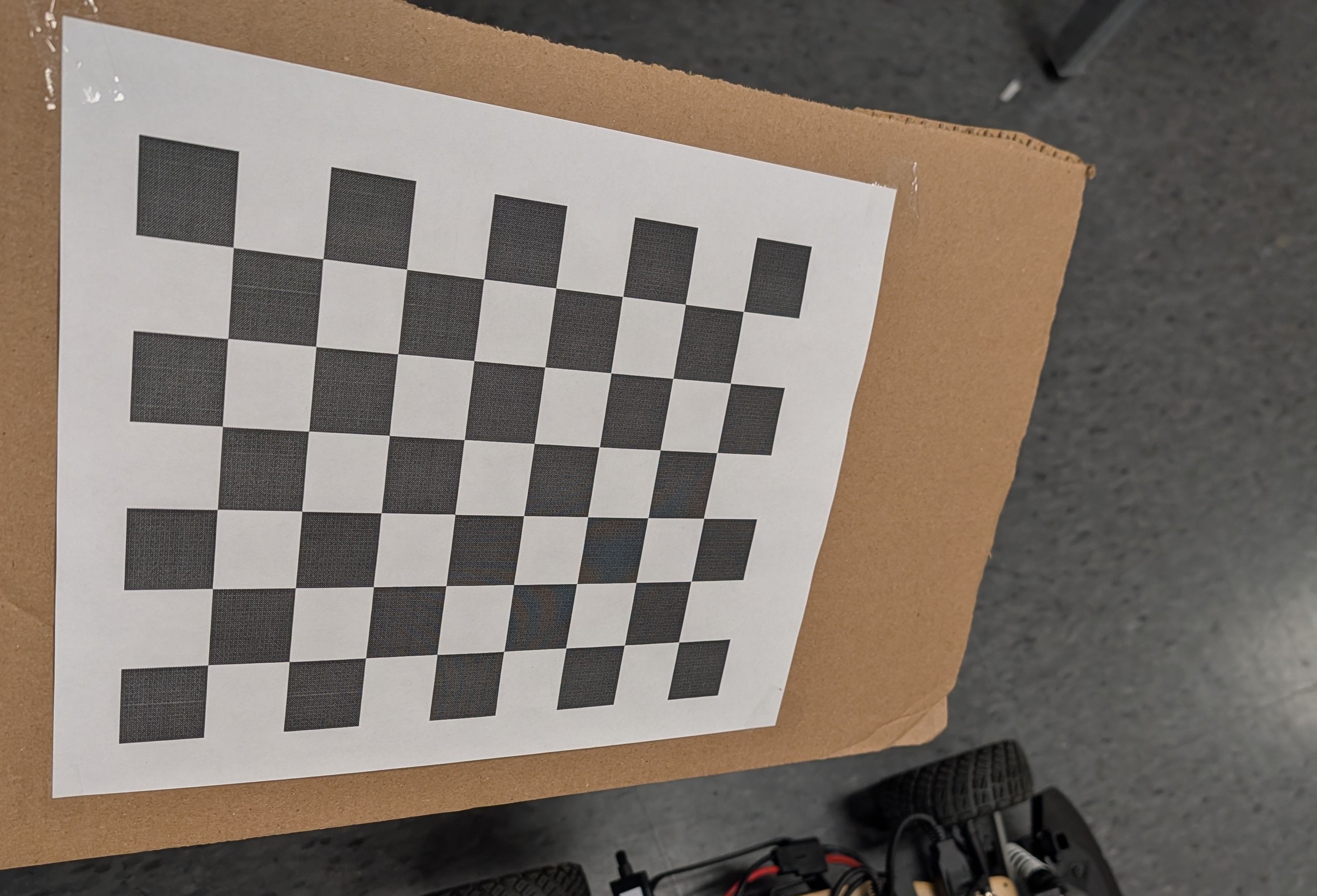
- Download the 8×6 checkerboard with 25 mm squares: Checkerboard-A4-25mm-8x6.pdf. If you generate a custom target, ensure the dimensions match the
--size 8x6 --square 0.025arguments passed to the calibrator in~/roboracer_ws/plans/camera_calibration.yaml. - Print at 100% scale and secure the sheet to a rigid, flat surface such as a book or clipboard so it stays perfectly planar during data collection.
2. Launch the Calibration Session
Calibration is the camera_calibration plan. Launching it opens a tmux session with one pane per node, each in its own container: the VNC desktop that the calibration GUI draws on (display :9), the camera node publishing /camera_0/image_raw, and the calibrator itself.
Airfield requires a workspace that has been migrated to it. Check for a
plans/folder and thescripts/buildfile in~/roboracer_ws. If your car has atmux/folder and acontainerscript instead, it is still on the older layout and you should follow the fallback instructions below. The full airfield reference for this workspace lives on the car at~/roboracer_ws/docs/AIRFIELD.md.
- Power on the car and confirm the camera is connected to the desired Orin
cam0port.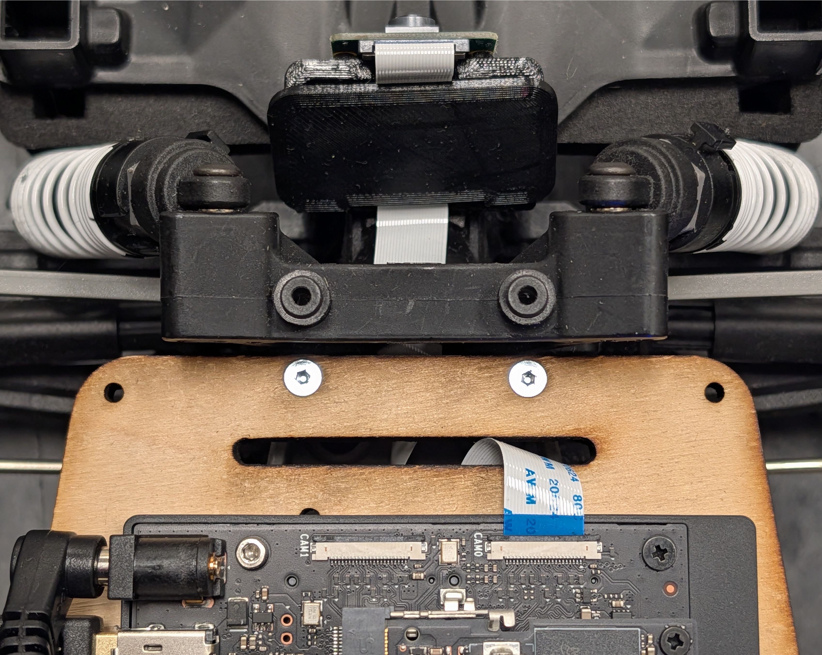
- ssh into the car and launch the calibration plan:
cd ~/roboracer_ws
SENSOR_ID=0 airfield project up camera_calibration
Use SENSOR_ID=0 for CAM0 or SENSOR_ID=1 for CAM1 to match the physical connector you are calibrating.
There is no container shell to enter first. Each pane starts its own container, and the
camera_calibrationtool is already installed in theut_automataimage that the calibrator pane uses.
Launch from your ssh shell, not from inside tmux
SENSOR_ID is expanded by the pane's shell when the plan starts, and tmux panes inherit their environment from the running tmux server — not from the command you just typed. If you launch the plan from inside an existing tmux session, the panes may see an unset SENSOR_ID and calibrate camera 0 no matter what you passed. Run airfield project down to tear down any previous session, then launch from a plain ssh shell.
Wait up to 15 seconds for the camera node to initialize and start publishing images. The camera pane deliberately waits 10 seconds before starting, so the VNC display is up before the GUI tries to draw on it.
If airfield fails: launch the calibration session with tmuxinator
The car previously started the camera and the calibration GUI from a tmuxinator configuration inside the container shell. This flow still works if airfield is unavailable, and it is the only flow available on a car that has not been migrated.
- Power on the car and confirm the camera is connected to the desired Orin
cam0port. - Inside a
./container shell, start the publisher and calibration GUI using the tmuxinator profile:
cd ~/roboracer_ws/tmux/camera_calibration/
SENSOR_ID=0 tmuxinator
Use SENSOR_ID=0 for CAM0 or SENSOR_ID=1 for CAM1 to match the physical connector you are calibrating.
3. Collect Calibration Views
Connect to the car using TurboVNC, at <your car>:5909. The plan's vnc pane is already serving that display, so there is no VNC server to start by hand. You should see the camera calibration GUI running:
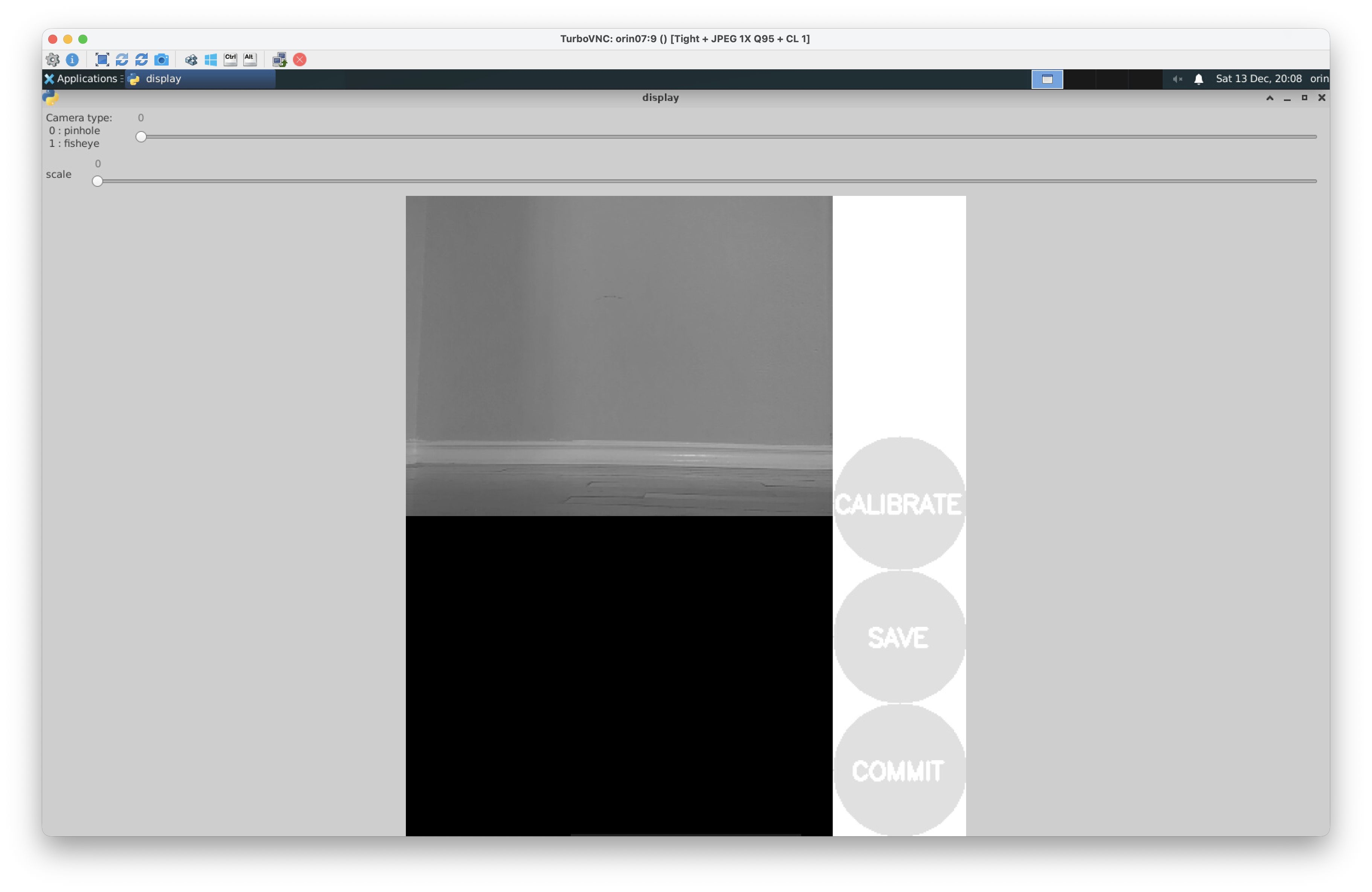
If no GUI appears, look at the calibrator pane. It waits for display
:9before starting, so it sits silently until thevncpane has the display up — and it keeps waiting if a previous session left a dead display behind. If it is stuck there, or it exited with an error about connecting to display:9, tear down withairfield project down(add--pruneif containers were left running after a crash or power loss) and launch the plan again.
- Watch the calibration GUI and move the checkerboard across the field of view. You'll see the rainbow overlay on the checkerboard when it is being detected.
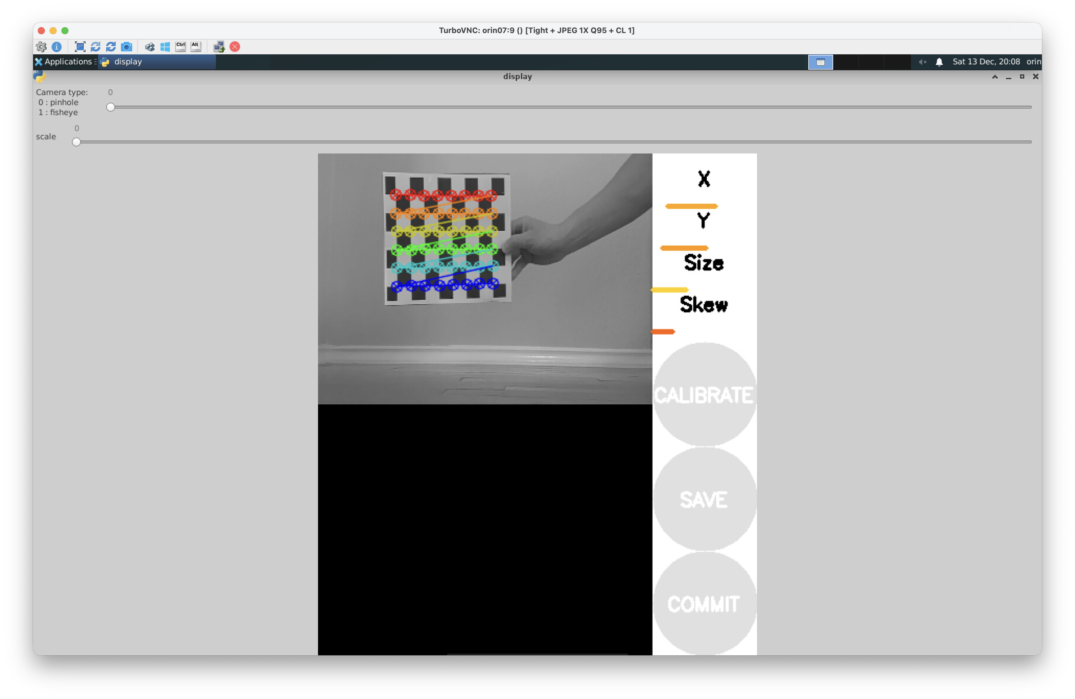
- Tilt the board, vary its distance, and reach all image corners. The calibration tool only collects data when the checkerboard is detected. If you do not see the rainbow overlay, move the checkerboard closer to the camera or tilt it until it is detected.
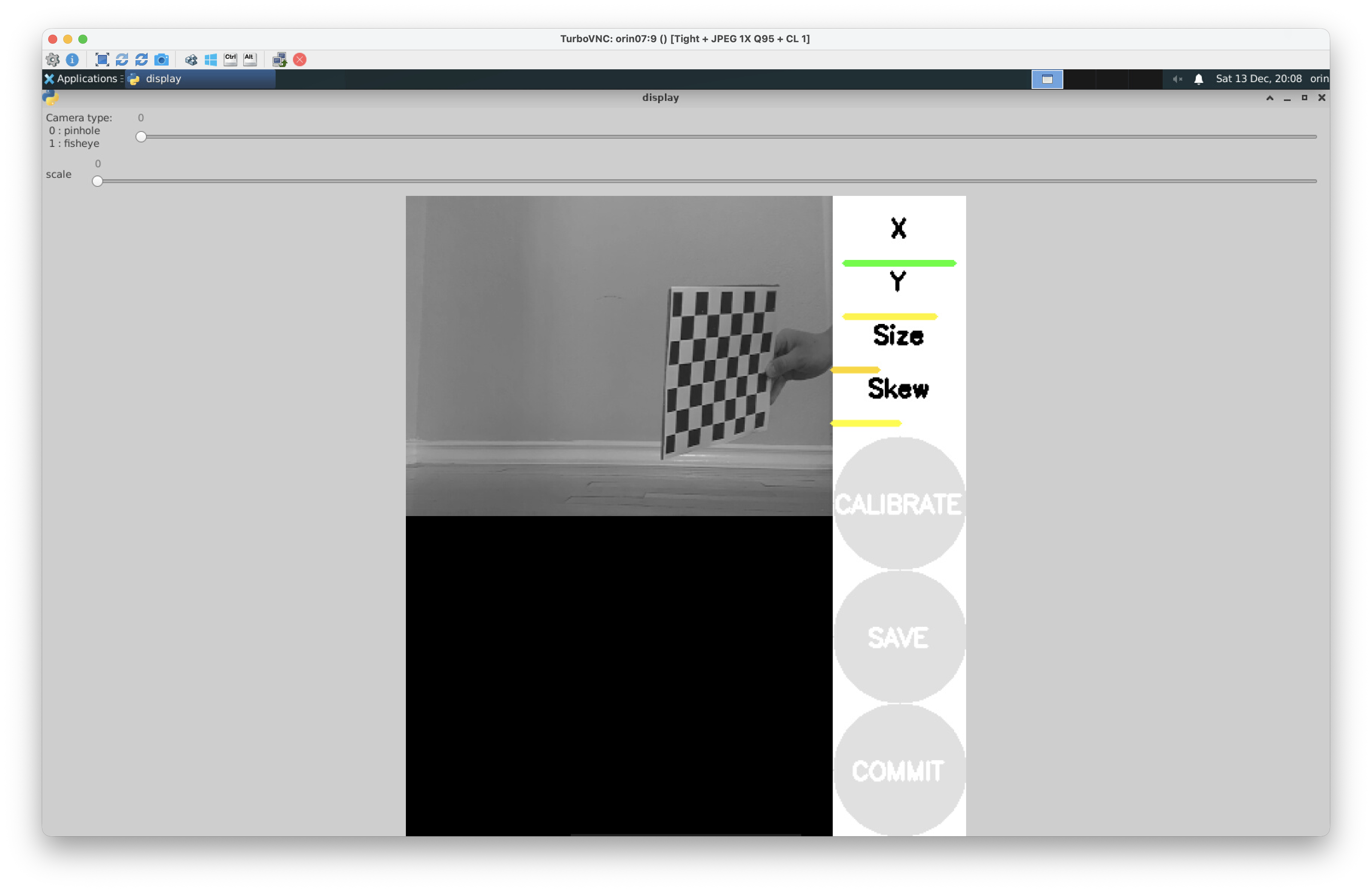 The progress bars above the Calibrate button will turn green once enough diverse samples are captured.
 - Once all the indicators turn green, stop moving the board and proceed to the next step.
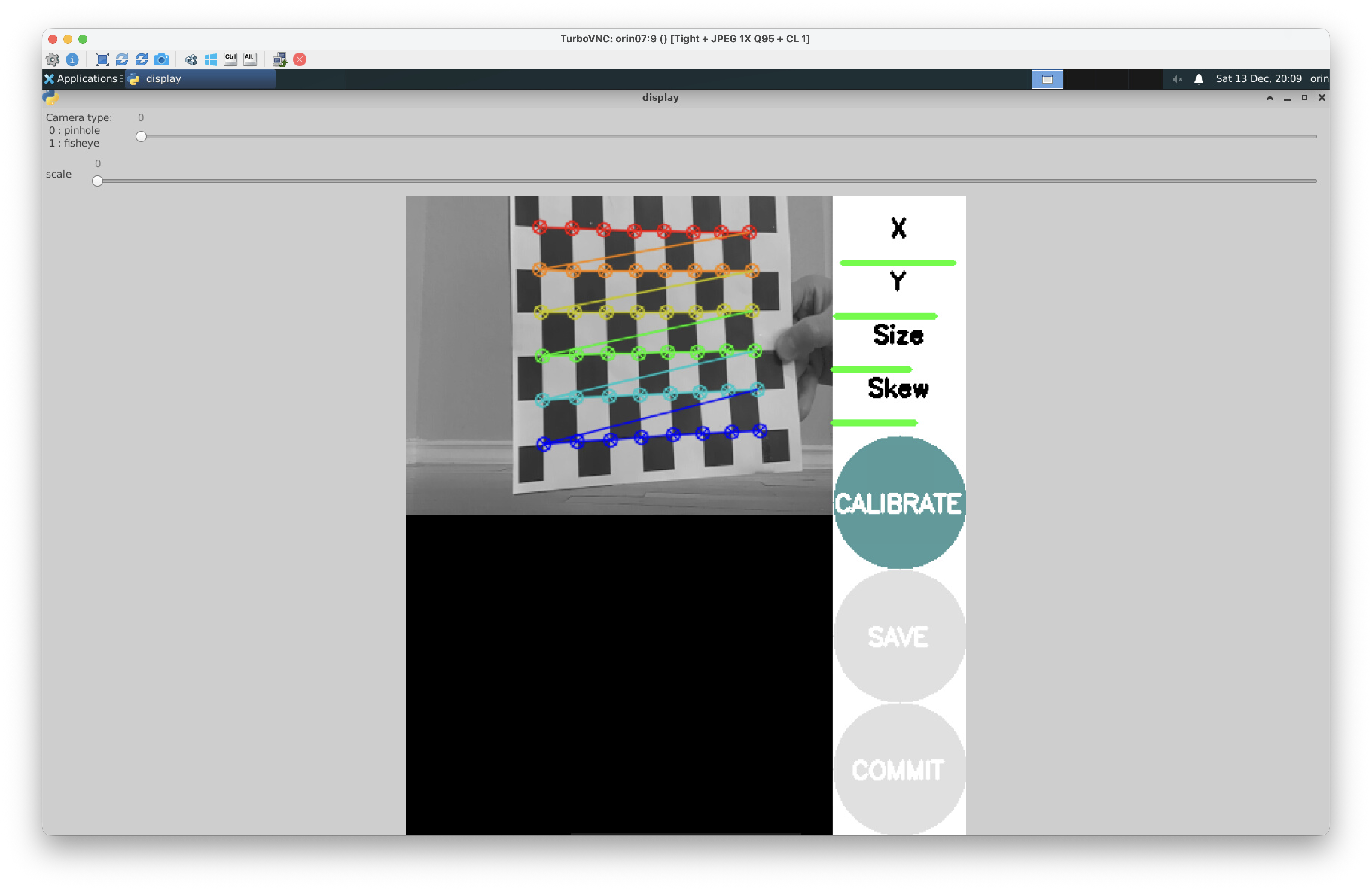
Tip: Due to the position of the camera relative to the screen on the car, this step is best conducted with one team member holding and moving the calibration board while another team member monitors the calibration GUI and directs the person with the calibration board.
4. Compute and Persist Intrinsics
-
Click Calibrate and wait several minutes for the solver to finish. When the calibration is complete, you'll see output like:
mono pinhole calibration...
D = [0.10166465392228333, -0.1535165177627402, 0.022056182296122145, -0.005469796503365781, 0.0]
K = [302.2040787524777, 0.0, 157.2380561691573, 0.0, 404.0513407332305, 158.10543185171142, 0.0, 0.0, 1.0]
R = [1.0, 0.0, 0.0, 0.0, 1.0, 0.0, 0.0, 0.0, 1.0]
P = [308.6962585449219, 0.0, 155.39091561775058, 0.0, 0.0, 407.4623718261719, 161.38296729964168, 0.0, 0.0, 0.0, 1.0, 0.0]
Click Save to persist the calibration results, you'll see output such as
('Wrote calibration data to', '/tmp/calibrationdata.tar.gz'), which is where the calibration data will be saved.That tarball is written inside the calibrator pane's container, not onto the car's filesystem, and airfield removes the container when the plan comes down. The numbers printed in the pane are what you need, so copy them out before tearing the session down. If you do want the tarball itself, copy it while the session is still running:
docker cp "$(docker ps -q --filter ancestor=airfield-pkg-ut_automata:latest | head -1)":/tmp/calibrationdata.tar.gz ~/. -
When the results appear, copy the reported matrices directly into
~/roboracer_ws/params/cameras/0/calibration.txt(or.../1/for CAM1) on the car itself, from your ssh shell. You will probably have to create this file. A representative output looks like:D = [0.10166465392228333, -0.1535165177627402, 0.022056182296122145, -0.005469796503365781, 0.0] K = [302.2040787524777, 0.0, 157.2380561691573, 0.0, 404.0513407332305, 158.10543185171142, 0.0, 0.0, 1.0] R = [1.0, 0.0, 0.0, 0.0, 1.0, 0.0, 0.0, 0.0, 1.0] P = [308.6962585449219, 0.0, 155.39091561775058, 0.0, 0.0, 407.4623718261719, 161.38296729964168, 0.0, 0.0, 0.0, 1.0, 0.0]
Hint: Use
vim ~/roboracer_ws/params/cameras/0/calibration.txtto create and edit the file.
- Once you've created this file, tear the calibration session down:
airfield project down
Always shut down with
airfield project downrather than closing the tmux session. Killing the tmux server leaves the package containers running in the background, and the camera's capture session stays held — the next launch then fails to open the camera.
Let the camera container see your calibration file
The camera node loads $HOME/roboracer_ws/params/cameras/<sensor_id>/calibration.txt from inside its container, and airfield mounts only the host paths it is told to. Check that the workspace's .air file lists the params directory:
grep params ~/roboracer_ws/.air
If that prints nothing, add this line under mounts: in ~/roboracer_ws/.air:
- ~/roboracer_ws/params
Paths listed there are mounted at the same path inside the container, and the container runs as your user with the same home directory, so the node finds the file exactly where it looks for it. .air holds per-machine settings and is not in git, so this is a once-per-car edit. Without it the camera pane logs Calibration file not found at /home/<user>/roboracer_ws/params/cameras/0/calibration.txt, proceeding without rectification, and /camera_0/image_rect never publishes.
The camera node reads the calibration file once, when it starts. Any session you had running while you wrote the file is still using the old values (or none), so the file only takes effect the next time you bring a plan up — which you do in step 7.
If airfield fails: persist intrinsics from the container shell
The steps above are the same, with two differences. The tarball written by Save lands in the container shell's /tmp, which is the same /tmp every node shares, and the whole workspace is mounted into that one container, so no .air entry is needed for the camera to read params/cameras/<sensor_id>/calibration.txt.
Once you've created the calibration file, close the calibration GUI: press ctrl-c in the tmux pane running the calibration GUI, then exit the container shell.
5. Calibrate Additional Cameras
If you have a second camera, repeat steps 2-4 with SENSOR_ID=1 and save the output under ~/roboracer_ws/params/cameras/1/calibration.txt. Make sure the first session is fully down before relaunching, so the new SENSOR_ID reaches the panes:
airfield project down
SENSOR_ID=1 airfield project up camera_calibration
Check the camera pane after it launches:
mono_processorprints the capture pipeline it opened, which starts withnvarguscamerasrc sensor-id=. If that readssensor-id=0when you asked for camera 1, the environment did not reach the pane — see the tip in step 2.
6. Camera and Lidar Extrinsics
Now that you've completed the camera intrinsic calibration, we will review the extrinsic calibration between the lidar and camera frames. The intrinsic calibration parameters describe the internal properties of the camera, while the extrinsic calibration defines the rigid body transform between the lidar and camera frames. Perfoming both calibrations allows us to accurately project lidar points into the camera image plane. Because the LIDAR and camera are rigidly mounted to the roboracer chassis, this information is published as a static transform in ROS.
The extrinsic calibration between the lidar and camera frames has already been measured for you. This transformation is then specified in the roboracer's robot description package, as the camera_connect joint between base_link and camera_frame.
The av_description package publishes those transforms. It runs in its own pane in the teleop plan you launch in the next step, so you do not normally start it by hand. To run it on its own:
airfield package cmd av_description -- ros2 launch av_description description.launch.py
Note:
airfield package cmd <package> -- <command>runs a single command in that package's container, building the image first if it does not exist yet. The robot description is launched automatically by most of the plans in the workspace.
If airfield fails: launch the robot description from the container shell
On a car that has not been migrated the package is named roboracer_description, and it is launched from inside the container shell:
ros2 launch roboracer_description description.launch.py
It is launched automatically in many tmuxinator configurations.
7. Project Lidar into the Image
- Now that you have created the camera calibration file you can launch the
teleopplan to start the camera, lidar, robot description, foxglove bridge, and teleop nodes:
cd ~/roboracer_ws
airfield project up teleop
The camera node picks up
params/cameras/0/calibration.txtas it starts, so this launch is the first one that publishes rectified images. If the camera pane logsproceeding without rectification, revisit the tip in step 4.
- Open Foxglove Studio on your laptop and connect to your car.
- Adjust the panels as follows:
- Ensure the Image panel is subscribing to
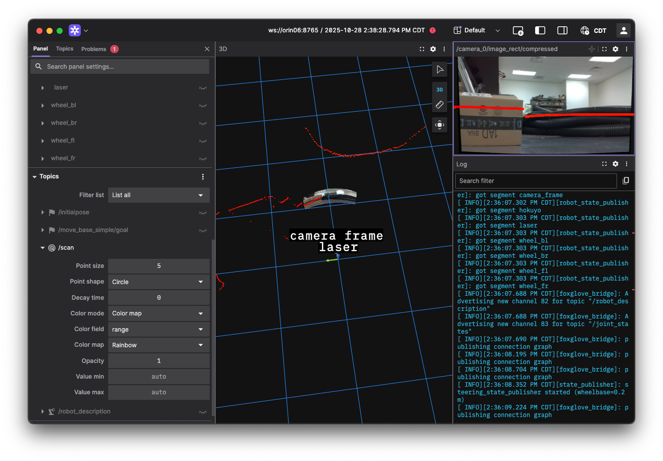
/camera_0/image_rect/compressedtopic to view the undistorted camera feed.You should notice the edges around the camera are no longer straight. This is because the internal distortion of the camera has been corrected and the pixels moved appropriately to project the image correctly onto the image plane.
- With the Image panel selected, enabled the
/scantopic by clicking the eye icon next to it in the topic list (left side). - Increase the
/scanmarker size until the points are visible. - Now you should be able to see the lidar points projected onto the undistorted camera image (shown on the right view).
- For debugging, it may also be useful to enable the camera view in the 3D panel to see the camera image projected into 3D space relative to the camera frame (shown on the middle view).
- Ensure the Image panel is subscribing to
- When you are done, tear the session down cleanly:
airfield project down
If airfield fails: launch teleop with tmuxinator
The car previously launched teleop from a tmuxinator configuration inside the container shell. This flow still works if airfield is unavailable, and it is the only flow available on a car that has not been migrated.
cd ~/roboracer_ws/tmux/teleop/
tmuxinator
The Foxglove steps above are unchanged: the topic names and the panel setup are the same either way.
Lab Notebook
Take a screenshot showing the projected lidar points overlaid on the rectified camera images in your lab notebook titled "Lidar Points Projected onto Camera Image".