Navigation
How does a robot know where it is in the world? Mapping and localization are fundamental problems in robotics that enable autonomous navigation. In this tutorial, you will learn how to run a Simultaneous Localization and Mapping (SLAM) algorithm to build a map of the environment while keeping track of the robot's position within that map. Then, you will use Adaptive Monte Carlo Localization (AMCL) to localize the robot on the map you've collected and then use the ROS2 Navigation Stack to navigate the robot to a goal.
Prerequisites
- Completed Intro to Car Hardware and Sensor Bring-Up, including building the workspace on the car with
scripts/build. All three sessions in this tutorial are airfield plans, and their panes launch from that shared build.
These are all provided in the plans you launch below.
- Lidar publishing
/scanat ≥10 Hz - The robot description node publishing the robot's static transforms
- The vesc driver node publishing odometry on the topic
/odom
Learning Objectives
- Students can build a map using SLAM and then use this map to allow their car to localize in the environment.
- Launch, inspect, and tear down the
car_calibration,record_map, andnavstackairfield plans. - Edit a package's configuration on the host and rebuild it so the running nodes pick up the change.
Tools and Packages
- We will be using the SLAM Toolbox package for mapping.
- The Hokuyo LIDAR is the primary sensor for both mapping and localization.
- The vesc_driver provides odometry information.
- Each of the three sessions is an airfield plan (
plans/car_calibration.yaml,plans/record_map.yaml,plans/navstack.yaml), launched as a tmux session with one pane per node.
Tutorial Steps
In this tutorial, you will perform car calibration, build a map using SLAM, and then run the navigation stack with AMCL for localization.
1. Car Calibration
Car calibration is essential to ensure that the vehicle's control commands correspond accurately to its physical movements. The calibration process involves tuning parameters for steering and speed to achieve precise control.
The calibration process is automated through the car_calibration plan and the script it runs. Launching the plan opens a tmux session with one pane per node, each in its own container: the calibration script, the joystick, the vesc driver, the on-car GUI, and the VNC desktop that the GUI draws on.
Airfield requires a workspace that has been migrated to it. Check for a
plans/folder and thescripts/buildfile in~/roboracer_ws. If your car has atmux/folder and acontainerscript instead, it is still on the older layout and you should follow the fallback instructions below. The full airfield reference for this workspace lives on the car at~/roboracer_ws/docs/AIRFIELD.md.
Start the car calibration plan after sshing into your car.
Note: You must run the car calibration from an SSH terminal and not the GUI because it requires you to interact with the script.
cd ~/roboracer_ws
airfield project up car_calibration
There is no container shell to enter first. Each pane starts its own container from the
ut_automataimage, and the calibration script is already installed in it.
When tmux launches, the left pane will contain instructions. The steps described here summarize and help describe the process that you will be guided through in the tmux session.
Where the script saves your calibration
Each step writes its result to car.lua, and on a migrated workspace there are two copies of that file: the source copy at ~/roboracer_ws/packages/ut_automata/config/car.lua, which is what you commit to git, and the installed copy under ~/roboracer_ws/.airfield/workspace/install/, which is the one the vesc driver actually loads. The script writes both, so a value takes effect as soon as you restart the vesc driver — there is no build step in the middle.
The script names the files it wrote in each save message, so you can confirm both were updated:
[INFO] [vesc_calibrator]: Updated steering_offset to 0.4555 in
  /home/orin/workspace/src/ut_automata/config/car.lua,
  /home/orin/workspace/install/ut_automata/share/ut_automata/config/car.lua
Those are the container's paths for the two host files above.
If airfield fails: run the calibration with tmuxinator
The car previously started the calibration from a tmuxinator configuration inside the container shell. This flow still works if airfield is unavailable, and it is the only flow available on a car that has not been migrated. In that layout there is only one copy of car.lua, at ~/roboracer_ws/src/ut_automata/config/car.lua, and the script writes it directly.
cd ~/roboracer_ws
./container shell
cd ~/roboracer_ws/tmux/car_calibration/
tmuxinator
Note: If you need to restart at any point, your progess will be saved at the end of each calibration step, so feel free to
ctrl-cto kill the calibration script and restart it later. You can skip completed steps by pressingqthenENTERwhen prompted at each step.
Steering Offset Calibration
This calibration step will find the servo position that makes the car drive perfectly straight.
Process:
-
Accept the dialog confirmation and then hold the
R1button. The car will drive forward at 1 m/s for 5 seconds -
Use the LEFT JOYSTICK (horizontal) to keep the car going straight
-
The script records how much steering correction you apply
-
After each run, the script shows your average correction and adjusts the offset
-
Repeat until your average correction is near zero (< 0.6 degrees)
How to Control:
-
Left stick horizontal (left/right): Apply steering corrections
-
Use small, smooth movements to keep the car tracking straight
-
DO NOT press any buttons during the test (triggers emergency stop)
-
Imagine you're actively driving to keep it on a straight line
Tips:
-
Use a long, straight line on the floor as reference (tape, hallway edge, etc.)
-
Focus on keeping the car centered on the line
-
Don't overcorrect - small adjustments work best
-
The script will tell you the average correction angle after each run
-
After 2-3 iterations, the car should need minimal correction
What the Script Reports:
-
Average correction angle (should converge toward 0°)
-
Standard deviation (how consistent your corrections were)
-
Maximum correction (peak steering input during the run)
-
Number of samples collected (~250 for a 5-second run)
Expected Result: steering_angle_to_servo_offset between 0.4 and 0.6
When the steering angle offset has been calculated, it will be automatically saved to the car.lua file. You will then be prompted to restart the vesc driver to apply the new settings. To do this, click the pane with the vesc driver and press ctrl-c to stop it. Then, restart it by pressing the UP ARROW key to recall the last command and then ENTER to run it again.
The pane's command is the host-side
airfield package cmd ut_automata -- bash -lc "ros2 run ut_automata vesc_driver --config_dir ...", soctrl-cstops the container andUP ARROW+ENTERstarts a fresh one. The driver readscar.luaonce, at startup, which is why restarting the pane is what applies a change.
You should then verify the newly calibrated offset is being used by checking the vesc driver output for a line like this:
[INFO] [1762804610.629546091] [vesc_driver_node]: steering_angle_to_servo_offset = 0.46
The value 0.46 should match the value printed out from the calibration script.
The final line in the vesc driver output should say Connected to VESC with firmware version 3.62 which indicates the vesc driver is running correctly and you can continue to the next step.
Steering Gain Calibration
This step will allow you to verify the relationship between steering angle and turn radius.
Process:
-
The car will make a full LEFT turn
-
After the turn, measure the DIAMETER of the circle it traced
-
Enter the diameter in meters
-
The car will then make a full RIGHT turn
-
Measure and enter the diameter again
How to Measure:
-
Mark the starting point before the turn
-
After the turn, measure across the widest part of the circle
-
Use a measuring tape for accuracy
-
Typical diameter: 2-4 meters
Record the Minimum Turning Radius
Record the minimum turning radius of the circle the car traced (in meters). You will use this value later in the tutorial in Section 3: Configure and Run the Navigation Stack with AMCL.
Tips:
-
Clear obstacles from the turning area
-
The car needs ~3-4 meters diameter space
-
If the car doesn't complete a full circle in 15 seconds, that's OK
-
Measure where the tires touched the ground
Expected Result: steering_angle_to_servo_gain around -0.9 to -1.1
When the steering angle servo gain has been calculated, it is saved to car.lua along with the max_steering_angle the script measured from your two turn diameters. Restart the vesc driver when prompted, the same way as before, and verify the new gain in its output:
[INFO] [1762804610.629528490] [vesc_driver_node]: steering_angle_to_servo_gain = -0.9227
The value -0.9227 should match the value printed out from the calibration script.
The final line in the vesc driver output should say Connected to VESC with firmware version 3.62 which indicates the vesc driver is running correctly and you can continue to the next step.
Speed Offset Calibration
This step will find the minimum motor command needed to overcome friction.
Process:
-
The car will gradually increase motor power
-
The script monitors when the car starts moving
-
This happens automatically - just watch for safety
What to Watch:
-
The car should remain stationary initially
-
Then begin to creep forward slowly
-
Be ready to press a joystick button if needed
Expected Result: speed_to_erpm_offset between 150 and 400
When the erpm offset has been calculated, it is saved to car.lua. Restart the vesc driver when prompted and verify the new offset in its output:
[INFO] [1762804610.629512906] [vesc_driver_node]: speed_to_erpm_offset = 330.00
The value 330 should match the value printed out from the calibration script.
The final line in the vesc driver output should say Connected to VESC with firmware version 3.62 which indicates the vesc driver is running correctly and you can continue to the next step.
Speed Gain Calibration
This step will calibrate the relationship between velocity commands and actual speed.
Process:
-
The car will drive at 0.5 m/s, 1.0 m/s, and 2.0 m/s
-
Each test runs for 5 seconds
-
The script calculates distance from odometry
-
You can optionally measure actual distance with tape measure
For Best Accuracy:
-
Mark a starting line
-
Mark lines at 1m, 2m, 3m, 4m, 5m, 10m
-
Watch which line the car reaches
-
Enter the actual distance when prompted
Tips:
-
The odometry-based measurement is usually sufficient
-
Manual measurement improves accuracy by 5-10%
-
A straight hallway or parking space works well
Expected Result: speed_to_erpm_gain around 5000-6000 (depends on gearing)
Commit your Calibration
Your calibration is now in both copies of car.lua, but only the source copy is tracked in git. Commit it so the values survive a rebuild and so your team has them:
cd ~/roboracer_ws/packages/ut_automata
git add config/car.lua
git commit -m "Calibrate car12"
A
colcon buildregenerates the installed copy from source, so the source copy is the one that has to be right. If you ever hand-edit a calibration value, edit~/roboracer_ws/packages/ut_automata/config/car.luaand rebuild withscripts/build ut_automata, rather than editing the installed copy under.airfield/.
Calculate Final Parameters
Two components that we will explore later in this tutorial are the relationship between the turning rate and the turning radius of the car. Using the measured turning radius from your calibrated parameters, we can compute the max turning rate as the arctangent of the ratio between the wheelbase and the turning radius.
maxTurnRate = atan(wheelbase / desired_min_turning_radius)
Compute your max turn rate using your measured turning radius from the steering gain calibration step. The wheelbase of the car is 0.324 m. Record your calculated max turn rate in your lab notebook, as described in the next step.
Test the Car's new Calibration
Drive the car around using the joystick and observe its behavior. In particular, when driving the car straight, it should maintain a straight trajectory with minimal steering corrections. If the car is drifting to one side, you may need to update the steering offset calibration. you can make a small positive change to the steering_angle_to_servo_offset value if it is drifting left, or a small negative change if it is drifting right. You can re-run just the steering offset calibration step to refine this value further.
Minor Adjustments
If you find later that the car is not moving in a straight line, you can make minor adjustments by tapping the right and left arrows on the PS4 Joystick D-Pad. Each tap will slightly adjust the steering offset and save this update to the configuration file.
The driver saves that trim to the car.lua it was given with --config_dir, which is the installed copy. That survives a driver restart but not a rebuild, so once you are happy with the trim, copy the final steering_angle_to_servo_offset into ~/roboracer_ws/packages/ut_automata/config/car.lua and commit it, as in Commit your Calibration above.
Record your Calibration Results
You can view the file to see all the calibrated parameters you applied:
cat ~/roboracer_ws/packages/ut_automata/config/car.lua
On a workspace that has not been migrated, this file is at
~/roboracer_ws/src/ut_automata/config/car.lua.
Which should look something like this:
car_name = "car12";
steering_angle_to_servo_offset = 0.4555;
steering_angle_to_servo_gain = -0.9676;
max_steering_angle = 0.3960;
speed_to_erpm_offset = 400.0;
speed_to_erpm_gain = 4082.8;
Lab Notebook
Record your final calibration parameters in your lab notebook for future reference.
It's important to keep a record of your experimental results independent of the code, in case you need to recalibrate or troubleshoot issues later. Write down the following parameters:
steering_angle_to_servo_offset= ___steering_angle_to_servo_gain= ___max_steering_angle= ___speed_to_erpm_offset= ___speed_to_erpm_gain= ___
Once you have applied and recorded your calibration, tear the session down:
airfield project down
Always shut down with
airfield project downrather than closing the tmux session. Killing the tmux server leaves the package containers running in the background, and the VESC serial port stays held — the next launch then fails to open it. After a hard crash or power loss, add--pruneto sweep any leftover containers.
2. Build a Map with SLAM Toolbox
Once your car is calibrated, you can build a map of your environment using SLAM.
The necessary nodes for mapping are configured in the record_map plan: SLAM Toolbox, the lidar, the vesc driver, the joystick, the robot description, the Foxglove bridge, the on-car GUI, the VNC desktop, and an rviz2 window on that desktop. Launch it from the GUI on the car or ssh into your car and run the commands:
cd ~/roboracer_ws
airfield project up record_map
Once the plan is up, connect Foxglove Studio to the car at ws://<your car>:8765. In the 3D window, visualize the /scan topic and the /tf tree to see the LIDAR data being published and the robot's frame transformations. Also, enable the /map topic to visualize the map as it is being built.
You can watch the same thing on the car itself instead: the plan's
rviz2pane opens a window on the VNC display, already loaded with~/roboracer_ws/rviz2/navstack.rviz, so connecting with TurboVNC at<your car>:5909shows the map, laser scan, and TF tree with no panels to configure. Both views can run at once.
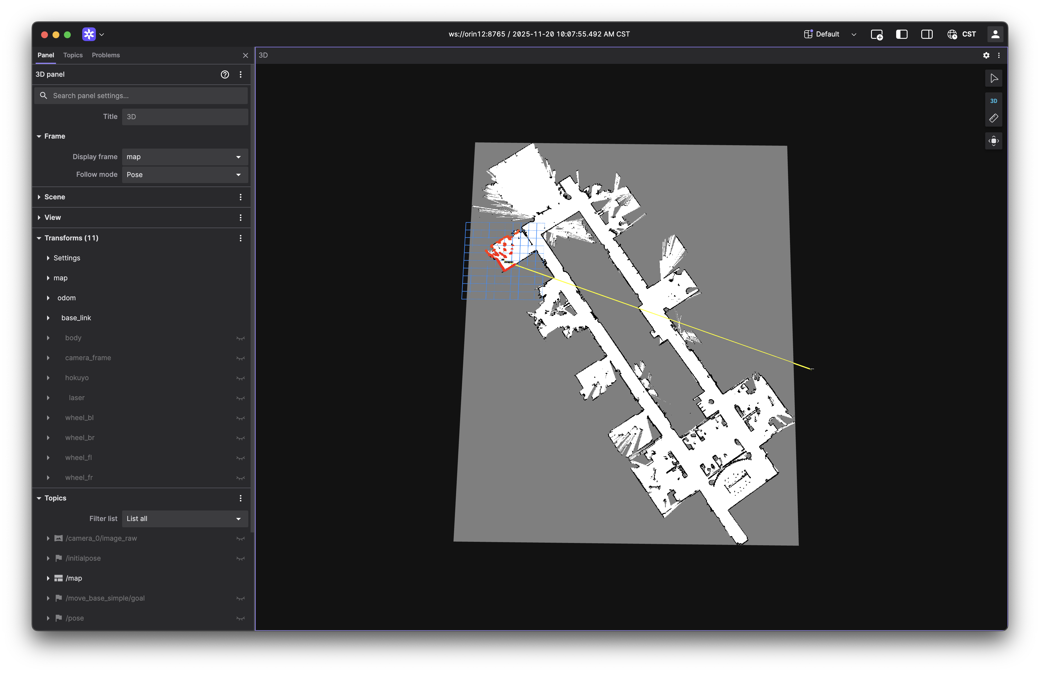
Teleoperate the car around the environment using the joystick. As you drive, observe how the SLAM algorithm builds the map in real-time. Here is what a sample mapping session looks like in Foxglove:
NOTE: Drive slowly and steadily to ensure accurate mapping. Fast and sudden movements can lead to poor map quality. If you find that the map is not building well, you may need to adjust the parameters of the SLAM algorithm, which are located in
~/roboracer_ws/packages/av_navigation/av_navigation/config/slam.yaml. That file is loaded from the installed copy of the package, not the source tree you edit, so a change needsscripts/build av_navigationand a relaunch before it takes effect — see the configuration step below.
Once your map is complete, save it with map_saver_cli. That tool lives in the av_navigation container, so run it through airfield, and write it into the package's source tree — $HOME/workspace/src/av_navigation inside the container is ~/roboracer_ws/packages/av_navigation on the car:
airfield package cmd av_navigation -- bash -lc 'ros2 run nav2_map_server map_saver_cli -f $HOME/workspace/src/av_navigation/av_navigation/maps/track'
Replace track with your desired map name. Run this from the plan's empty first pane, or from a second ssh session, while the record_map plan is still up — map_saver_cli subscribes to the /map topic that SLAM Toolbox is publishing, and the topic disappears when you tear the plan down.
$HOMEis in single quotes so the container's shell expands it, not your host shell. The two are not always the same path.
Ensure your map is saved by checking the maps directory on the car for the generated .pgm and .yaml files:
ls ~/roboracer_ws/packages/av_navigation/av_navigation/maps/
gdc_3n.pgm  gdc_3n.yaml  home.pgm  home.yaml  track.pgm  track.yaml
Your new map is now in the source tree, but the navigation launch file loads maps from the installed share directory, so build the package to install it:
cd ~/roboracer_ws
scripts/build av_navigation
Then tear the mapping session down:
airfield project down
If airfield fails: build the map with tmuxinator
The car previously launched the mapping nodes from a tmuxinator configuration inside the container shell. This flow still works if airfield is unavailable, and it is the only flow available on a car that has not been migrated. The Foxglove steps above are unchanged.
cd ~/roboracer_ws
./container shell
cd ~/roboracer_ws/tmux/record_map/
tmuxinator
Save the map from inside the container shell. There is only one copy of the package in this flow, so there is nothing to install afterwards:
export MAP_NAME=track  # Choose a name for your map
ros2 run nav2_map_server map_saver_cli -f ~/roboracer_ws/src/av_navigation/av_navigation/maps/${MAP_NAME}
3. Configure and Run the Navigation Stack with AMCL
Now that you have built a map, you can use it for localization with AMCL. Before running the navigation stack, you need to update the configuration files with your calibrated parameters.
Update the Navstack Configuration
Update the main nav2 configuration file ~/roboracer_ws/packages/av_navigation/av_navigation/config/nav2.yaml with your calibrated parameters. Specifically, update the following sections, using your calibrated turning radius value from the previous step, the default is set to 0.8:
Hint: Use the minimum turning radius you measured during the Steering Gain Calibration step. If you did not record it, just use the default value of 0.8.
controller_server:
  ros__parameters:
    FollowPath:
      AckermannConstraints:
        min_turning_r: 0.8

planner_server:
  ros__parameters:
    SmacPlannerHybrid:
      minimum_turning_radius: 0.8
Then update the max_curvature value, which is the inverse of the turning radius. It is set where the twist_to_ackermann node is created, in ~/roboracer_ws/packages/av_navigation/av_navigation/launch/navigation.launch.py:
    twist_to_ackermann_node = Node(
        package='av_navigation',
        executable='twist_to_ackermann',
        name='twist_to_ackermann_converter',
        output='screen',
        parameters=[{
            'input_topic': 'cmd_vel',  # Nav2 controller output
            'output_topic': '/ackermann_curvature_drive',  # VESC driver input
            'wheelbase': 0.324,  # meters, should match vesc.lua config
            'max_curvature': 1.25,  # 1/x = 1.25 (x is your minimum turning radius)
        }]
    )
Edit navigation.launch.py, not twist_to_ackermann.launch.py
The package also ships a standalone twist_to_ackermann.launch.py with its own max_curvature launch argument. The navstack plan does not use it — it runs navigation.launch.py, which creates the node directly with the parameters shown above. Editing the standalone launch file has no effect on the plan.
Both of these files are read from the installed copy of the package, not from the source tree you just edited, so build av_navigation to install your changes:
cd ~/roboracer_ws
scripts/build av_navigation
This is the same reason
car.luaneeded a copy into the shared build. Every airfield container mounts the one shared workspace at~/workspaceand the launch files resolveconfig/,maps/, and their own paths throughget_package_share_directory, which points into~/workspace/install. Source edits reach the running nodes only after a build.
Run the Navigation Stack with AMCL
Now that you have a map, you can use it for localization with AMCL. The necessary nodes for localization are configured in the navstack plan: nav2 and AMCL, the camera, the lidar, the vesc driver, the joystick, the robot description, the Foxglove bridge, the on-car GUI, the VNC desktop, and rviz2. Launch it from the GUI on the car or ssh into your car and run the commands:
cd ~/roboracer_ws
MAP=track airfield project up navstack
Substitute
trackwith the name of your saved map if different. With noMAPset, the plan falls back to thegdc_3nmap that ships with the package.
Launch from your ssh shell, not from inside tmux
MAP is expanded by the pane's shell when the plan starts, and tmux panes inherit their environment from the running tmux server — not from the command you just typed. If you launch the plan from inside an existing tmux session, the nav2 pane may fall back to gdc_3n no matter what you passed. Run airfield project down to tear down any previous session, then launch from a plain ssh shell.
Once the nodes are running, connect to the car using the TurboVNC Client:

You should see an rviz2 window when you connect to the car via TurboVNC. The plan's rviz2 pane starts it for you, loaded with ~/roboracer_ws/rviz2/navstack.rviz.
If you don't see the
rviz2window, look at therviz2pane. It waits for display:9before starting, so it sits silently until thevncpane has the display up. If it is stuck there, or exited with an error about connecting to display:9, tear down withairfield project down --pruneand launch the plan again. To start it by hand instead:airfield package cmd rviz2 -- bash -lc 'DISPLAY=:9 rviz2 -d $HOME/roboracer_ws/rviz2/navstack.rviz'
If airfield fails: launch the navstack with tmuxinator
The car previously launched the navigation stack from a tmuxinator configuration inside the container shell. This flow still works if airfield is unavailable, and it is the only flow available on a car that has not been migrated. In that flow there is no separate installed copy, so the configuration edits above take effect with no build step.
cd ~/roboracer_ws
./container shell
cd ~/roboracer_ws/tmux/navstack/
MAP=track tmuxinator
The rviz2 steps below are unchanged.
To help AMCL identify the correct position of the car, you should publish an initial pose estimate. This tells the algorithm where to being its search for the cars current location. Click the "2D Pose Estimate" button in the toolbar and click + drag on the map to set the initial pose.
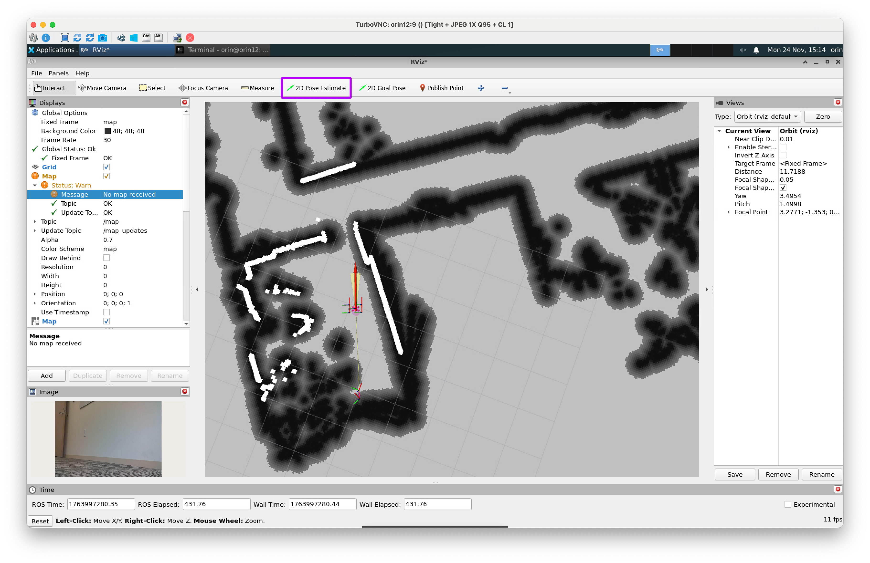
Once you've selected the correct position and orienation for the car, AMCL will begin to localize the car in the environment and you should see the car's position and orientation update in the rviz2 window.
You've now localized the car!
Classical Navigation
Now that the car is localized, we can use the classical navigation stack to make the car move to a specific location on the map.
First, set the desired goal pose by clicking the "2D Nav Goal" button in the toolbar and click + drag on the map to set the goal pose.
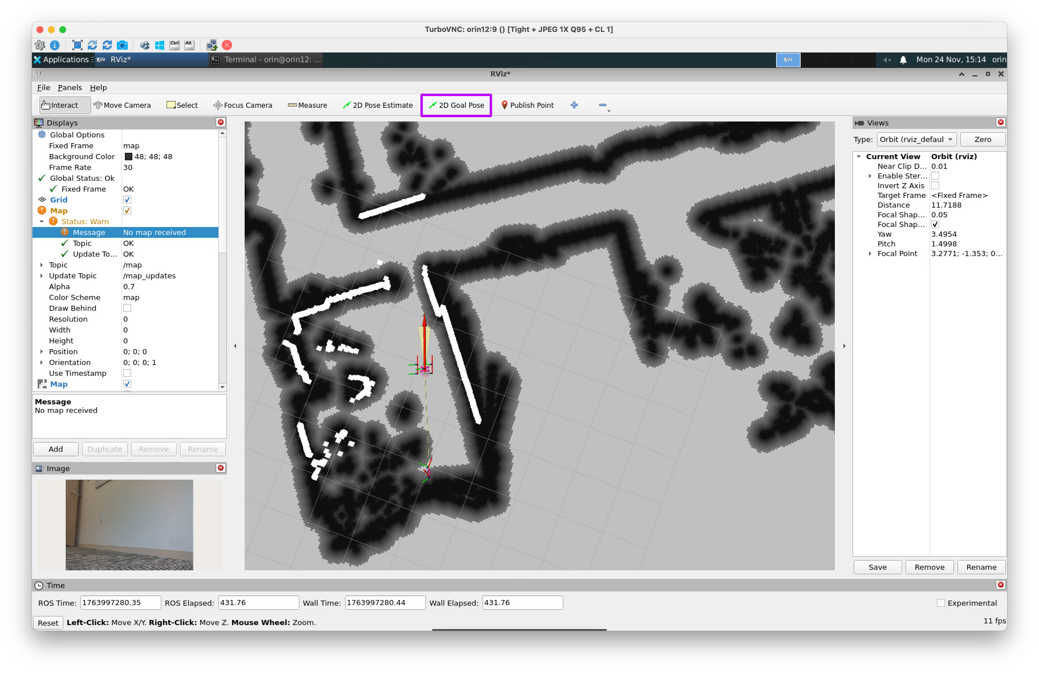
After setting the goal pose, hold the R1 button on the PS4 Joystick to allow the car to move.
Lab Notebook
Record several videos of the car moving to different locations on the map. Observe the car as it moves and identify any issues with the localization or navigation behavior. Try moving to some locations in front of the car and some locations behind the car. How does the car perform in these different scenarios? Write down your observations in your lab notebook.
When you are done, tear the session down cleanly:
airfield project down
As with the other two sessions, always shut down with
airfield project downrather than closing the tmux session, so the containers stop with it and the VESC, lidar, and camera are released.
Follow-up Questions
Respond to the following questions in your lab notebook:
-
Now that your car can localize and navigate to specific points on a pre-recorded map, how would you make the car navigate a racetrack autonomously using the classical navigation stack? What would a python script that could do this look like?
-
What are some issues that you encountered while configuring the localization and navigation stack? How did you resolve these issues?